


Jeroen's
Jeroen's
Technical Corner
Technical Corner
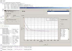
Simulation software, tube electronics and more
Mathematics of tube models
| |
The mathematical models used in Motega are based on work performed by Norman Koren. I only made a minor modification to his tube models, which gave me a slightly better result. It should be noted that I do not pursue a 'perfect' tube model. For allmost every tube that you may use, the tube models generated by Motega are accurate within a few percent and that's more than enough for my (and likely your) purposes. Keep in mind that datasheets only describe a typical behavior of the tube in question: if you take 10 new tubes then you'll find that none of them will fit the datasheet within a few percent...
In the following 3 sections I'll give the mathematical models for diodes, triodes and tetrodes/pentodes. Because there is already so much said about this topic on the internet, I will not elaborate on these models further here. Diode model
Motega uses a diode model which consists of an ideal 'lossless' diode in series with a resistor r. The voltage across the Motega diode model therefore consists of two components:   Triode model
Calculation of the triode anode current starts with making the exponential factor xa dependent of the anode voltage Va. This is in fact the only modification I made to the original model of Norman Koren:    Tetrode/pentode model
Equivalent to the calculations of the triode anode current, calculation of the tetrode/pentode anode current starts with making the exponential factor xa dependent of the screen grid voltage Vg2:    |


